Locate the photovoltaic function
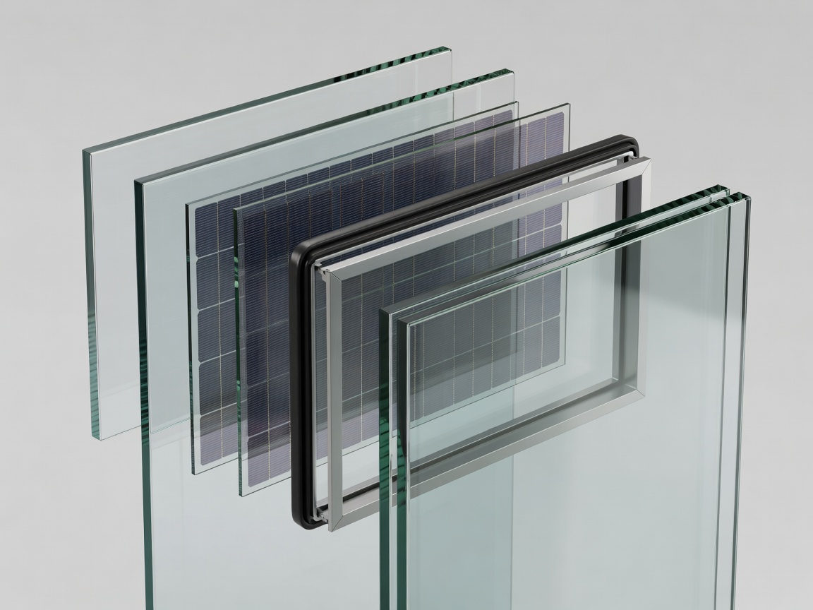
A building window can contain multiple glass panes, low-emissivity coatings, gas-filled cavities, spacers, laminates and protective layers. Adding photovoltaics changes this stack. The first design question is where the active material sits and what protects it. Its position affects exposure to moisture and heat, optical interactions, electrical routing and the direction in which absorbed heat flows.
An attractive film measured on a small glass substrate does not establish the behaviour of that complete stack. Additional interfaces can change reflection and transmission. Processing temperatures may be incompatible with other layers. Adhesives and sealants can introduce chemical compatibility problems. These issues are not peripheral manufacturing details: they help determine whether the laboratory performance survives assembly.
Keep thermal and daylight duties intact
Glazing must manage heat as well as light. A low U-value can reduce conductive heat transfer, while the solar heat gain coefficient or g-value describes a different pathway. A photovoltaic layer alters the balance between transmitted, reflected and absorbed solar energy. Some absorbed energy becomes electricity, but the remainder still participates in the thermal balance.
In a heating-dominated climate, reducing solar gain may remove useful winter heat. In a cooling-dominated building, lowering heat gain can be helpful, but the benefit depends on orientation, shading and controls. Reduced visible transmission can also increase electric lighting demand unless daylight remains sufficient and the lighting system responds appropriately. The correct comparison is therefore an annual building assessment against a credible reference window, not electricity generation considered in isolation.
Design the edge as carefully as the centre
Edges concentrate several problems. Insulated glazing units need durable seals and spacers. Photovoltaics need conductors and connections. Luminescent concentrators may need edge-mounted cells. Bringing these functions together can introduce thermal bridges, moisture pathways, local heating and inaccessible components. A cable leaving a pane must not compromise the weather barrier or create an unsafe electrical arrangement.
Shading is another system-level issue. Mullions, adjacent buildings, overhangs and dirt can produce uneven illumination. Depending on the electrical architecture, partially shaded elements can limit current or require protective measures. A façade containing many small panes also needs a practical wiring strategy, compatible power electronics and documented isolation for servicing. These questions belong with qualified façade and electrical professionals.
Qualification is a set of boundaries
IEC 61215 concerns design qualification and type approval of terrestrial photovoltaic modules, while IEC 61730 addresses photovoltaic module safety qualification. IEC 63092 addresses photovoltaics in buildings. These standards provide important frameworks, but citing a standard number does not establish that a particular product has passed relevant tests or satisfies every local building requirement.
Glazing requirements may separately address impact, load resistance, fire behaviour, weather tightness, thermal properties and durability. EN 1279 is relevant to insulating glass units; EN 14449 concerns laminated glass and laminated safety glass product conformity. Applicability depends on the product, location and current regulatory framework. Evidence should identify the tested assembly, test laboratory, report scope and any exclusions.
Standards context: International Electrotechnical Commission and CEN-CENELEC. Standard summaries are not substitutes for the complete documents or professional compliance review.
Durability includes replacement
Accelerated exposure tests can reveal degradation pathways, but passing a test sequence is not a direct prediction of service life. Real windows encounter combined stress: temperature cycling, humidity, sunlight, mechanical movement and cleaning. Electrical output can decline before a pane becomes visibly unacceptable, while seal failure or delamination can create problems unrelated to initial conversion efficiency.
A service plan should identify what can be replaced independently. If an electrical connection fails, must the entire glazing unit be removed? Can technicians isolate a single pane? Are replacement units likely to match the appearance and electrical characteristics of adjacent panes? These are practical design questions even when a device’s initial performance is strong.
End-of-life planning also belongs in the assembly discussion. Laminates, coatings, conductors and active materials may complicate glass recovery. A credible sustainability assessment considers material processing, replacement, expected output and recovery pathways rather than assuming that all power-generating glass is environmentally beneficial by definition.
A useful project evidence sequence
- Specify the complete glazing stack and reference window.
- Measure optical, thermal and electrical properties on representative assemblies.
- Evaluate façade loads, weather resistance and electrical safety.
- Model orientation, shading, controls and annual energy effects.
- Plan inspection, isolation, replacement and material recovery.
This sequence does not guarantee a viable product. It makes the unresolved questions explicit before a material claim becomes a façade commitment. The next step is to examine how much of this sequence has actually been demonstrated.
Examine deployment evidence →